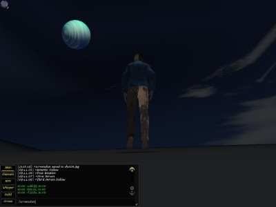
My client-side Eulora task set last week is completed and as a result, the Testy character gets now to see something more than just fog in his Sphere-of-all-beginnings, look:

Testy under a Wavy-Blue Moon, in the Sky-Sphere of all beginnings.
It turns out that CS can indeed eat – though not very willingly 1 – “geometry” for fixed/static entities (aka “generic meshes”) even without any xml in sight 2. For static aka non-moving entities, there are 5 sets of numbers required:
- Vertex coordinates
- Normals at vertices
- Colours at vertices
- Texture mappings at vertices
- Triangles
The main trouble with the above was the exact “how” and “where” to actually set them so CS understands what they are. It turns out that the most obvious “those are the vertices and those are the normals etc” approach is “obsolete” and replaced apparently by having to specify a render buffer for each set of numbers. Of course it’s still the same arrays of numbers either way, but with render buffers you need to also specifiy which *type* of render buffer you have in mind (i.e. what are those values for) and in pure CS style this is specified by giving the… name. Name that is afterwards internally translated into a numerical id of course but nevermind since it’s supposedly as easy as it can get to have to remember that the name is exactly “position” and not “positions” nor “vertices” nor anything else 3). So easy in fact that I ended up having the list of “buffer names” at hand all the time, great help indeed.
Before moving on to some basic descriptions of those 5 sets of numbers, it’s worth noting that they are just the most usual 5 sets really: there are plenty others that one can specify though it’s unclear exactly when and precisely why would one do. The easiest example concerns texture coordinates: one can specify as many as 4 different texture mappings. And why stop at 4 if one went all the way there, why not 5 or 6 or 7 or 1000? No idea. Anyway, for the basic descriptions:
Vertex coordinates are exactly what the name says: the 3D coordinates of vertices that define the entity’s shape in space. Those are all relative to the position at which the entity is drawn at any given time, of course, since they are internal to the entity and unaware of anything else in the larger world.
Normals at vertices are perpendiculars on the surface of the entity at each of the vertices defined earlier. Those are quite important for lighting (together with the orientation of each triangle surface defined further on).
Colours at vertices specify the colour of the object at each vertex and allow therefore colouring of the full object through interpolation for instance. While in principle this can be skipped when a texture is given, the “skip” simply means default colour (black) so it’s a “skip” only in the sense that it’s less obvious it exists.
Texture mappings at vertices – those are tuples (u,v) that specify a texture point (2D because textures are 2D images) that is to be mapped precisely to each vertex. Just like vertex coordinates provide fixed points for the shape of the engine that is otherwise interpolated at non-specified points, the texture mappings provide fixed points for the “painting” of the shape with a given texture.
Triangles define the surface of the entity as approximated through triangular shapes. All surfaces of static shapes in CS are approximated through triangles and the only difference between curved and flat surfaces is essentially in the number of triangles required so that your eye is fooled enough so you like rather than dislike the lie. This is after all the whole computer graphics in a shell: a lot of effort spent to lie to you the way you like it.
Triangles in CS are given as triplets (A,B,C) where the values are simply indices of the vertices previously defined. So the simplest cube will have for instance 8 vertices for its 8 corners as well as 2*6=12 triangles for its 6 faces since each face, being a square, needs 2 triangles to approximate. And those 12 triangles mean 36 values in total since each triangle needs the indices of all its 3 vertices. Moreover, the order in which the vertices are specified matters as it gives the orientation of the approximated surface 4 and that in turn is crucial for calculating lighting (and ultimately for figuring out whether you get to even see what is on that surface at all). Since it’s not intuitive perhaps, it’s worth noting the basic fact that a surface has 2 sides and the “painting” of a texture is strictly on one side only. So if you mess up the surface’s orientation, you can easily do the equivalent of dyeing a garment on the inside without any colour whatsoever showing when you wear it unless you turn it first inside-out.
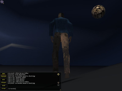
As you might have guessed from the above example with the most basic cube if from nothing else, even very simple entities require a lot of values tediously and boringly specified – hence quite the bread and butter of automation 5, yes. For now and for testing purposes, I simply extracted the numbers of interest from the xml description of the moon object in game and then I used them as default values for an object created directly from code. And lo’ and behold, Testy got a moon to stare at and the moon even got to paint itself stony when I’m bored of its usual wavy blue:

Stony Moon and Testy in the Sky-Sphere.
The next biggish step further in this line is to figure out how to generate terrain from just a heightmap and then how to create an animated (hence, Cal3D) entity from code rather than through the sterile xml-packaging. Looking even further from there, monstrous xml-shaders await in the same direction but in other directions there is still a lot of work to do on teaching the PS code to use the EuCore library and to discover as a result that the world is way larger than what fits in its inherited, well-worn and time-proven, traditional xml-bible.
- A bit like those finding out that they can actually eat food that was never packaged in plastic or washed in chlorine or even re-heated.[↩]
- At least not in geometry-sight. In a bit wider perspective, all shaders so far are still balls of xml that will probably have to be untangled sooner rather than later.[↩]
- If you give a non-existent name, the buffer is simply ignored since supposedly you can define your own buffers too so it’s not an error. Combined with the wonderful way in which everything influences everything else in graphics, you get – if you are lucky – to puzzle over some unexpected visual effect that might even seem at first to have nothing at all to do with the names of the render buffers at all (maybe you messed up a few numbers in that long list, you know?[↩]
- By convention, vertices are given clockwise as read when facing the surface[↩]
- Automation can be here exporters from supported tools such as Blender and generators of known shapes/patterns.[↩]
Comments feed: RSS 2.0
[…] as in getting the height right turns out to be only half (the reasonably well-working half) of the terrain task: once I had in place at least the generic mechanism for creating factories and meshes, the terrain […]
[…] Loading a static (incapable of movement) object given through its list of vertices, normals at vertices, colours at vertices, texture mappings at vertices and triangles that make its faces. This includes already loading factories and textures. […]
[…] http://ossasepia.com/2019/07/08/the-rocky-moon-notes-on-graphics-for-eulora-ii/ << Ossa Sepia Eulora — The Rocky Moon (Notes on Graphics for Eulora, II) […]